- cross-posted to:
- main
- cross-posted to:
- main
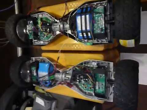
This experiment will show how easy the Hoverboard controller can be manipulated. As shown in the video a TxD signal was given to all 4 inputs of the two motor controllers. In a robot project that would of course be a bit different. Then 2 UART (2x TxD) would drive the 4 wheels, per side a motor controller with 2 wheels.
Config of the USART-Communication: 22500,N,9,1. That means 22500 Baud with 9 Data-Bits, no Parity, one Stop-Bit.
Example of the data transfer:
Data to send 6 Bytes (9 Bit) for STOP (Speed= 0000): 100h, 000h, 000h, 000h, 000h, 055h
Data to send 6 Bytes for 10% FORWARD (Speed= +0150d): 100h, 000h, 096h, 000h, 096h, 055h
Data to send 6 Bytes for 10% BACKWARD (Speed= -0150d): 100h, 0FFh, 06Ah, 0FFh, 06Ah, 055h
Range for the variable “Speed” (decimal): -1600 … 0 … +1600
But I have seen different Motor-Controller with some Variation in the Speed-Range and Baud-Rate, so everyone have to figure out the Value for a specific Motor-Controller…
- Uploader: AccuXperT
- Uploader url: https://www.youtube.com/@accuxpert2277


similar
https://hackaday.io/project/158256-hoverbot/log/146069-assembling-hoverbot