
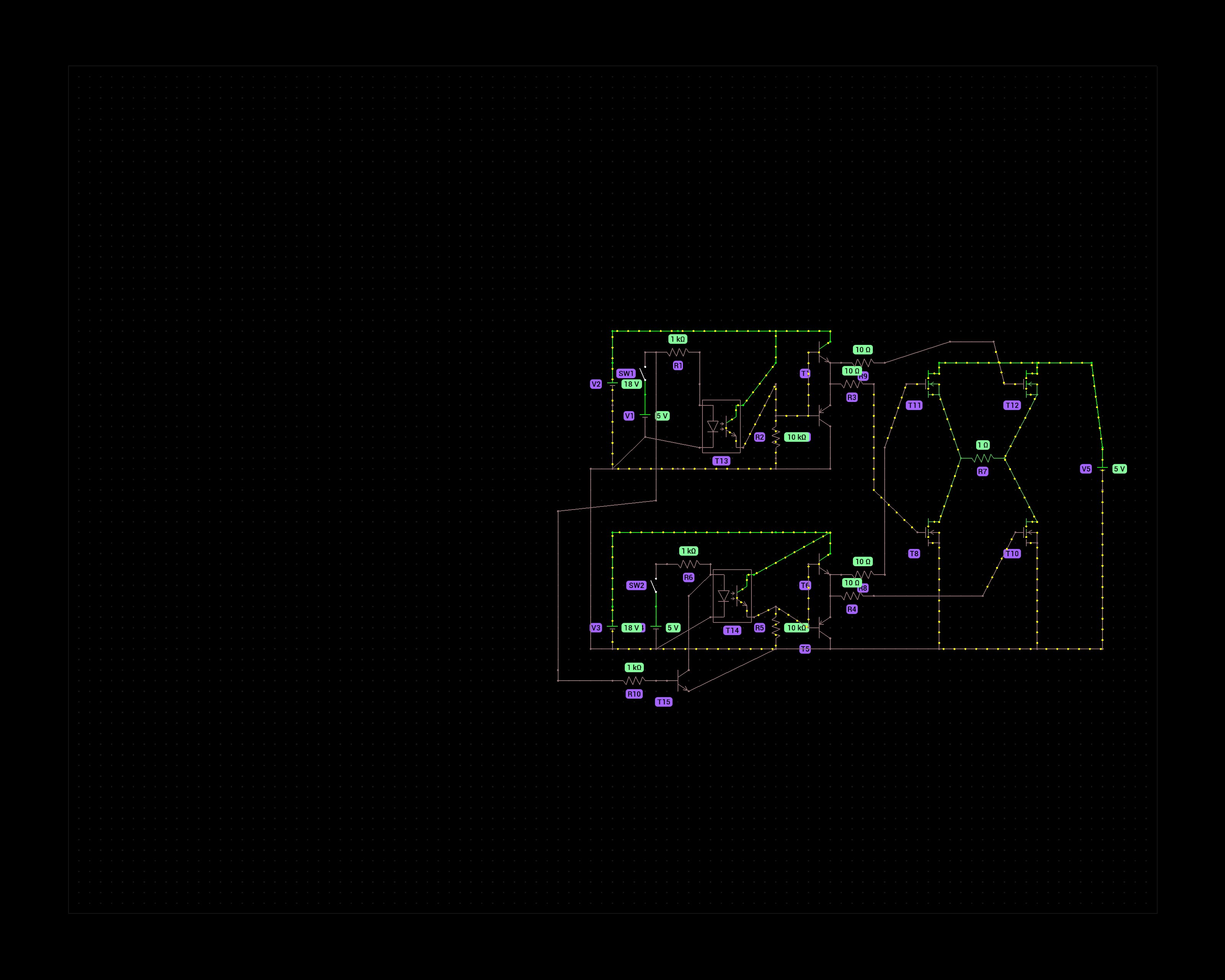
Thanks again for the advice. I made a working prototype and attached it to my pump. The PCB is also made at home which is something I’m trying to learn.
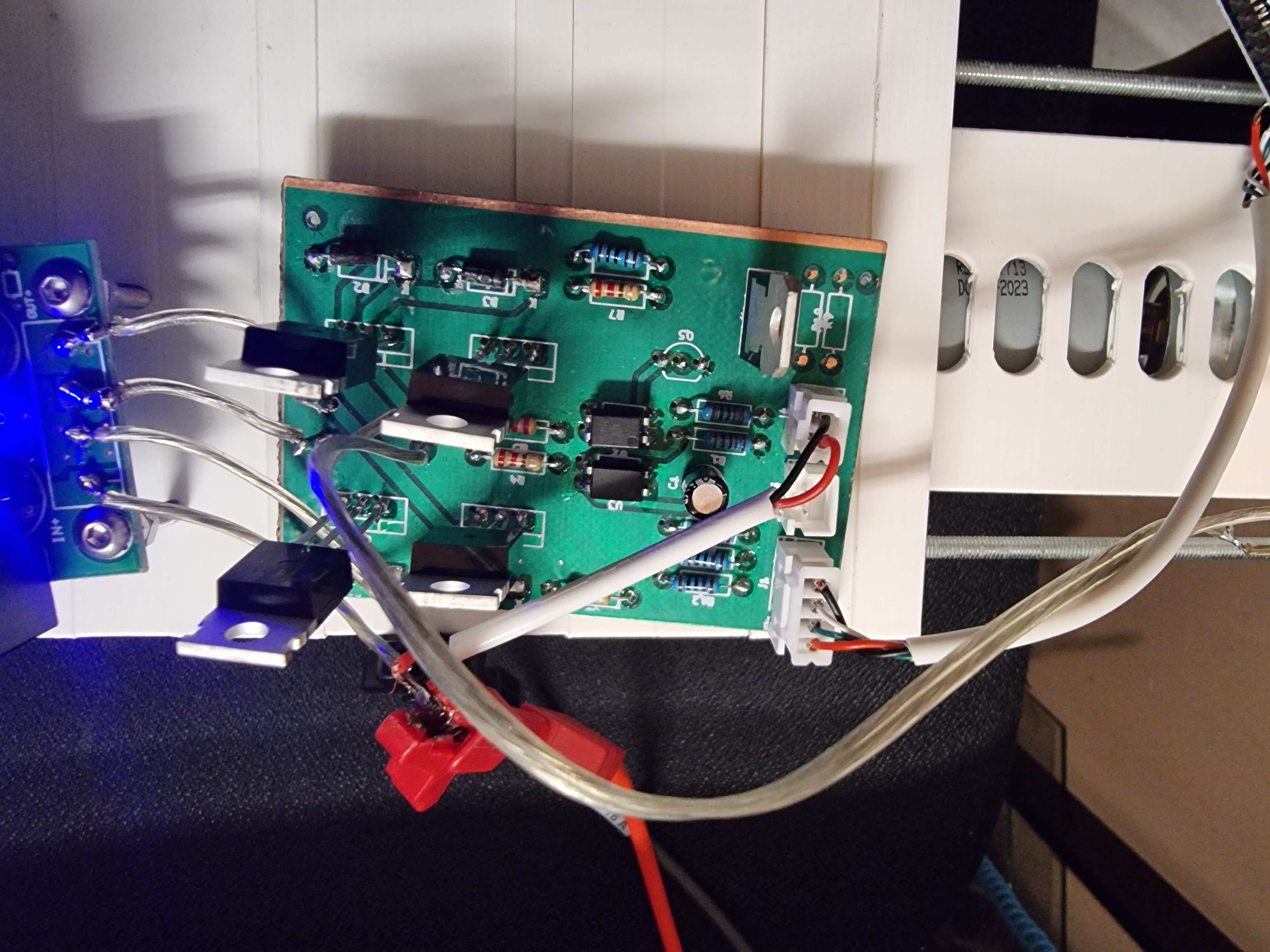
For now I’ve used just optocouplers to drive the mosfets, since pulling p-type gates down to above -24V seemed like a hassle. I’ve ordered some IR2210 gate drivers and intend to use those with PWM later to not have to use a buck converter.
Here’s a video of the pump. https://drive.google.com/file/d/1qKDBLTbYi2Fbu3UOXpxqSoj00oueWK-K/view?usp=sharing
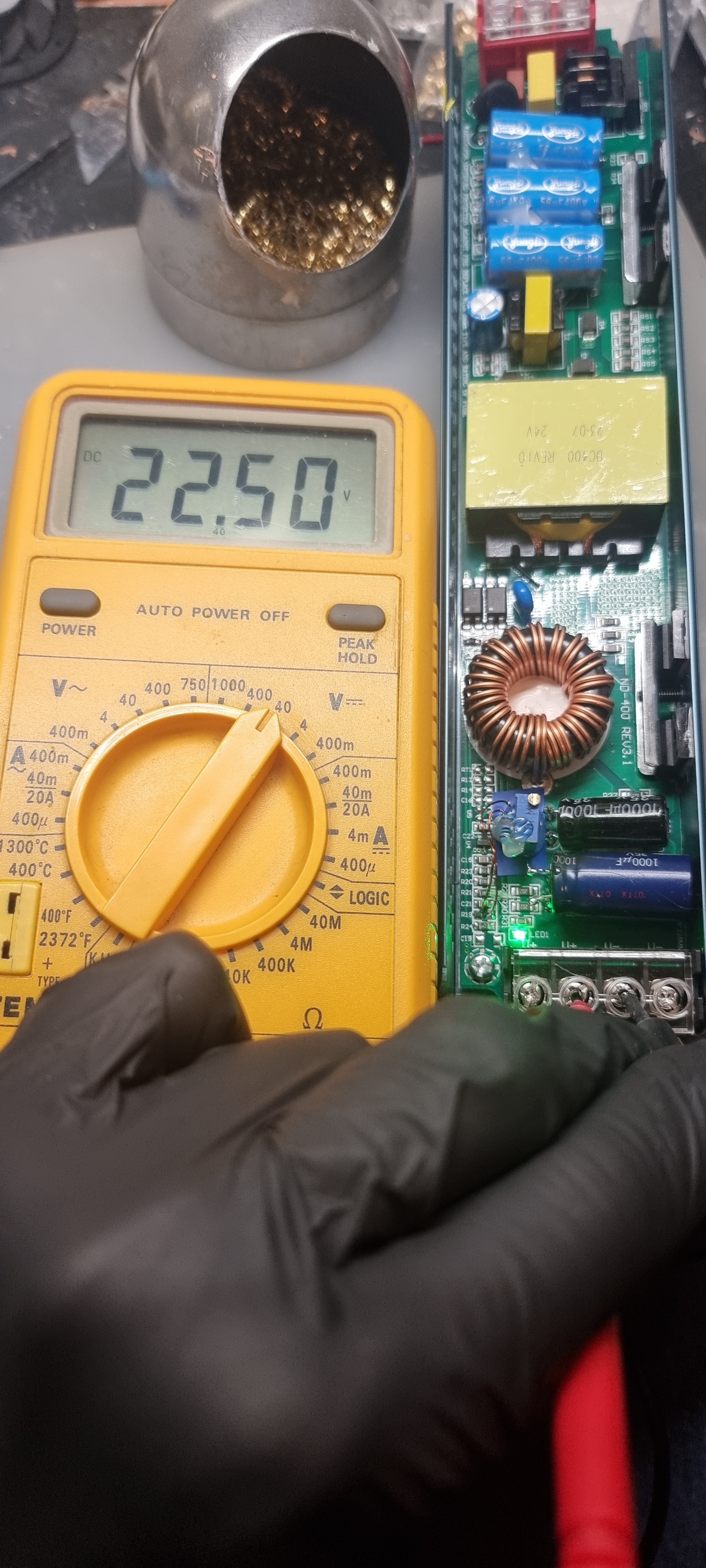
And the pump in action. https://drive.google.com/file/d/1--HyeJGtYS5dgsjgelE6CrOm2vbBmwXU/view?usp=sharing This version has a stepper motor instead of a DC motor. Stepper motors have low speed limit which is why I’m trying to change it to DC motors.
I just got cheap stuff such as an 858D hot air station. Any Chinese clone will do and a TS100 soldering iron. Nowadays the Pinecil would be a better choice.