• 3 Posts
  • 13 Comments
Joined 1 year ago
cake
Cake day: June 20th, 2023

help-circle
  • Great, good luck with that :)

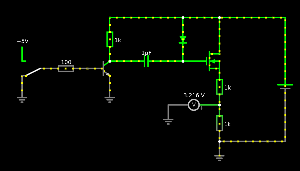
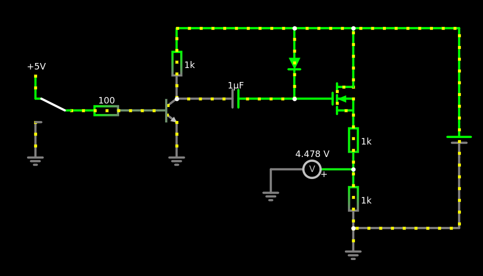
    Another thing that comes to mind: for audio purposes another technique used in ring modulators for audio effects is to use a mosfet switch to mix the signal with a square wave. This has more byproducts than mixing with a pure sine, but is a lot easier to do. Since you are downconcerting, it should not matter at all if you use a square wave, since the byproducts will all be (higher-order) harmonics of the local oscillator, which you’ll filter out anyway.


  • It’s not completely stupid. One pissible issue: when the light level is around the threshold, slight variations (think: cloud passing by) will cause the relay to switch back and forth quickly. This can be solved with some additional parts (keyword: hysteresis).

    I would recommend using a microcontroller, it makes this problem easy to solve, plus you can have more logic to trigger the lights (eg time based).

    Another thing is turning off: if it’s purely based on light level, you need to make sure the sensor does not “see” any of the LED light, otherwise it thinks the sun is back up


  • Hm, I don’t understand how this is supposed to work - is that a n-channel or p-channel FET?

    When I sketch it using falstad’s circuitjs, it looks like the FET (n-channel) is a little bit on all the time

    and fully on, when a pulse is applied

    Source:

    spoiler
    $ 1 0.000005 10.20027730826997 50 5 43 5e-11
    r 144 80 144 176 0 1000
    r 0 192 96 192 0 100
    t 96 192 144 192 0 1 -8.999999980890745 9.099999980846458e-10 100 default
    c 144 176 304 176 0 0.000001 -1.7996761414451612e-8 0
    f 304 176 384 176 32 2 0.02
    d 304 80 304 176 2 default
    r 384 192 384 272 0 1000
    r 384 272 384 352 0 1000
    g 384 352 384 384 0 0
    g 144 208 144 256 0 0
    w 144 80 304 80 0
    w 384 160 384 80 0
    w 384 80 304 80 0
    v 528 256 528 208 0 0 40 9 0 0 0.5
    w 528 256 528 352 0
    w 528 352 384 352 0
    w 528 208 528 80 0
    w 528 80 384 80 0
    g -48 208 -48 256 0 0
    R -48 176 -48 128 0 0 40 5 0 0 0.5
    S 0 192 -48 192 0 0 false 0 2
    p 384 272 272 272 3 0 0
    g 272 272 272 304 0 0


  • You could probably increase the 82K and 10K resistors to be much bigger

    That’s what I thought initially, but this stackoverflow post dissuaded me. The argument there is that the measurement will be wrong, if the input current is not enough to charge the internal cap within the measurement period. But I’ve done some testing now, and measurements done with 820k and 100k agree well with what my voltmeter measures, so I’ll go with this solution!

    a fresh alkaline 9V battery is actually 9.6V or more, not 9V.

    Indeed! 9.6V * 10k/92k = 1.04V is still below 1.1V, so I should be fine in this case :)

    9V battery voltages droop noticeably when under load because of their high internal resistance. Make sure to measure under the same conditions.

    This is a good point!

    My firmware will be pretty monotonic though, basically:

    1. wake up
    2. measure battery
    3. measure some other sensors (the actual task of the device)
    4. turn on a transceiver, send all the measurements (including battery voltage)
    5. turn off transceiver & go to sleep

    So, the load should be always the same at step (2).