• 0 Posts
  • 5 Comments
Joined 1 year ago
cake
Cake day: June 7th, 2023

help-circle
  • A car output is going to be ~12-14Vdc and the solar panel at 24V. You do not want to connect those two together. Ideally you have some kind of switch that connects the input to the bluetti only to the solar panel or only to the car outlet, and to the car output only if it is present. You can probably use a contactor or a heavy duty relay that is 12V and connect the NC contact to the panels, NO to the car, and COM to the bluetti. Add a capacitor to dampen spikes whenever the system switches and connect the grounds together. A bjt jank, and also have to check the relay ratings / coil power usage


  • It really depends how much power/current you are switching. If you are switching 1A with a beefy heatsink FET, the time spent in the linear region is short enough it shouldn’t be a problem. If you are switching 50A though it then you might have a problem. Depending on how that gate divider is set up, you could still potentially damage the gate of the FET when shorting it to ground to discharge it if I understand how its hooked up correctly.

    Ideally you would use some kind of FET driver with a voltage source (e.g. linear regulator) to turn on and off the gate plus the gate resistor.


  • Like you said, you can power the 5V rail directly from the buck converter. You can also set the fuses to use the lower frequency internal oscillator. Another good option is that for most of the time, you should keep the atmega in the sleep/low power state, and use an interrupt from a timer to wake the mcu occasionally. You can probably also set up pin change interrupts to wake the mcu as well if say a button is pushed. Additionally, you might be able to disable some of the peripherals if not in use - I haven’t looked at AVR microcontrollers in a while so this might not be applicable.

    A final option if you really really need it to have low power is to use an external timer ic that turns power on and off to the Arduino. These can have extremely low power draw, and are used on things like door and window sensors to extend their runtime to years by almost eliminating power draw when the mcu isn’t running - even the mcu sleep state draws a significant amount of power on large time scales


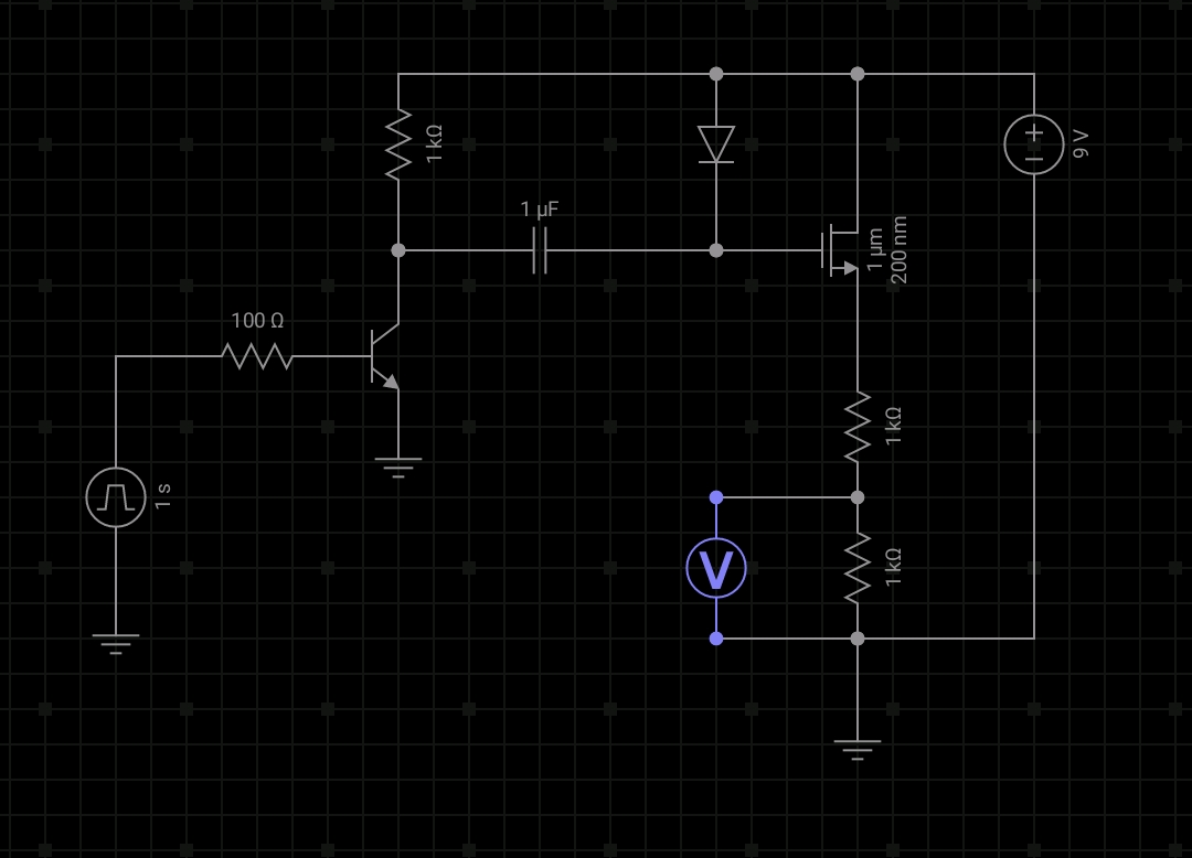
  • It is an N channel FET. The concept is called “bootstrapping” since Vgs needs to be greater than Vth for the MOSFET to be on. When the FET is on the high side and you want the full 9V on the output, you use the diode to charge the capacitor, and the other side of the cap is 0V. Then, when the other side of the cap is connected to 9V, the charge on the cap can’t go anywhere so the voltage on the other side jumps to 18V. This creates a Vgs of 9V. Ideally you would have something better to drive the gate to fully turn off the FET, but I just used a quick and dirty driver where the bootstrap capacitor directly feeds the gate instead of being the input to the driver. Because if this, the Vgs doesn’t drop completely to 0