
1·
11 months agoThose adapters should definitely be fine for 24 V. Running the fans off 19 V will probably work, but they will run at slightly slower RPM (probably not a big problem for a filter).
Those adapters should definitely be fine for 24 V. Running the fans off 19 V will probably work, but they will run at slightly slower RPM (probably not a big problem for a filter).
You could use a voltage divider followed by a unity-gain amplifier to lower the output impedance, about like this:
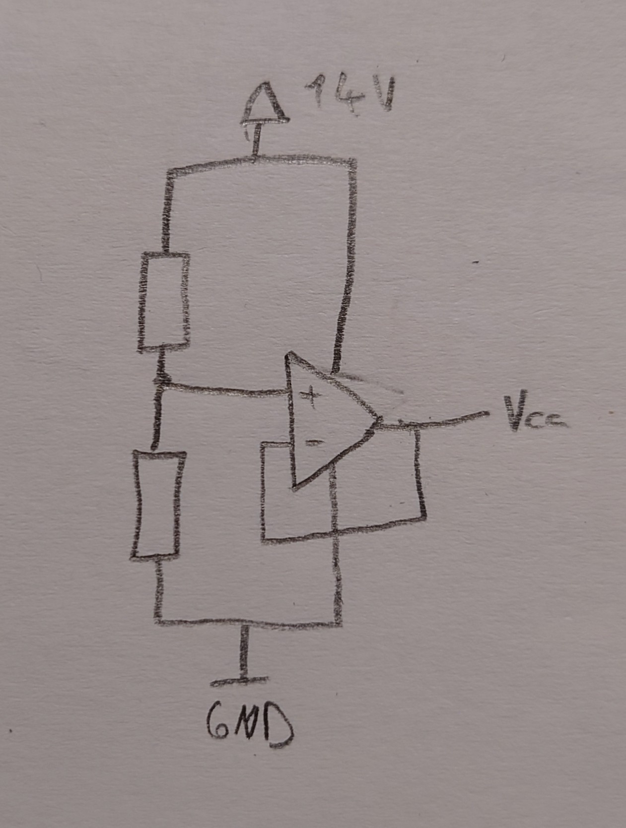 (I think that circuit could work, but I haven’t thought about it a lot, so it might not)
Not really. With that bulb, all the light is focused forward, not to the side. The light will never hit the reflector, it is only focused by the lens in the LED housing, and that isn’t enough.
From looking at the LED bulb, I can tell you that it will not work very well in that flashlight.
The reflector of the flashlight is built so light coming from a very small source (like the filament of an incandescent bulb) is directed forward in a focused beam. With the led bulb, light is coming from 10 different spots, none of them being in the focus point of the reflector. The result will be a spread out beam that won’t be bright over longer distances.
The only type of LED bulb that could work is something like this car replacement bulb that keeps the light source to a relatively small spot. But I don’t think those are available in the size you need.
3
From a cursory read of the datasheet, using the “dead time control” pin seems to be the way to go. Basically, this pin is used to set the voltage, while the error amplifier inputs (that’s the closest function to “over current protection” this chip has) are used to adjust the output according to the load. For your application, you probably don’t need to use them at all.
My instinct would be to disable the error amplifiers by connecting pins 1,2,15 and 16 to GND. You can then connect the wiper pin of the potentiometer to the deadtime control input, with the other pins of the potentiometer connected to GND and 3.3 V.
I haven’t worked with this chip before, so take this with a grain of salt. You should probably use a simulation tool to check the circuit before you start destroying chips.