• 1 Post
  • 5 Comments
Joined 1 year ago
cake
Cake day: July 23rd, 2023

help-circle
  • For what it’s worth, I didn’t mean take the sensor out of the wall, but just electrically unplug it from the controller to see what it does on its own when you turn on the water.

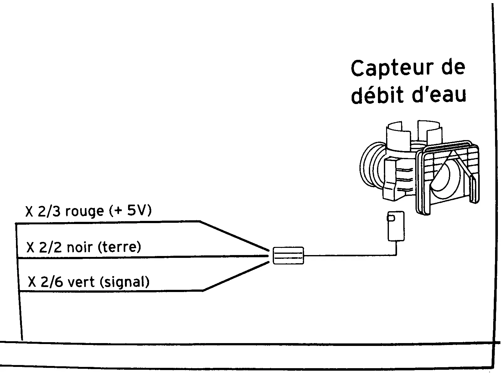
    Yeah I figured that but the terminals on the sensor are hard to reach so I was figuring I would need to remove it. But then it occurred to me that I could leave the thing in place and do the isolated test by unplugging the X2 connector from the motherboard and easily access the pins through that connector. So that’s what I did. Results:

    • at rest, the signal wire is 4.75 V
    • water running, the signal wire is 2.3 V

    So in isolation the sensor worked correctly. Then I plugged it back into the motherboard and retested to confirm again the bad voltages. But in fact the readings were correct. It’s unclear why it works now. I wonder if the unplugging and replugging of the x2 connector improved a connection that deteriorated somehow.

    Thanks for saving me €36! However incidental. If I had not done the test in isolation, I probably would not have messed with the X2 connector. I would have normally just replaced the sensor as an experiment.

    (edit) I can hear a ticking sound coming from the motherboard. I’m not sure how long it’s been doing that. It’s quite faint unless I put my ear close to the board. Maybe it’s normal.


  • It shows 5V on the diagram but I don’t think that’s precise. I measured the red wire at 4.68v which is around what the guy in the video got in his test. Since the board is part of the circuit I suppose I cannot rule out the board as a problem. Testing the sensor in isolation will be rough going because it’s a proprietary joint. So I would have to get a tight rubber hose and fit that onto a garden hose. For powering it I have a switchable ac adapter with a 4.5 V setting. Or I can maybe get 5V off a USB charger or ATX PSU from a PC. My multimeter does not have a frequency function but I can see from the video that it would be useful for this so I might look for 2nd hand multimeter at the next street market, though that will set me back a week (OTOH might be worth it if it helps diagnose this in a way that helps avoid buying the wrong part).

    Whatever is broken here, it was something that gradually failed. For several months it was a gamble when turning on the hot tap whether the boiler would detect it and give hot water. It was like a 50/50 game of chance for a while then getting hot water became progressively less likely until it flatlined.


  • It shows 5V on the diagram but I don’t think that’s precise. I measured the red wire at 4.68v which is around what the guy in the video got in his test. Since the board is part of the circuit I suppose I cannot rule out the board as a problem. Testing the sensor in isolation will be rough going because it’s a proprietary joint. So I would have to get a tight rubber hose and fit that onto a garden hose. For powering it I have a switchable ac adapter with a 4.5 V setting. Or I can maybe get 5V off a USB charger or ATX PSU from a PC. My multimeter does not have a frequency function but I can see from the video that it would be useful for this so I might look for 2nd hand multimeter at the next street market, though that will set me back a week (OTOH might be worth it if it helps diagnose this in a way that helps avoid buying the wrong part).


  • Yeah, if by /in system/ you mean connected to the board. I didn’t mess with anything other than to stick my probes onto the wires. The boiler is not switching on to heat water and it acts just as if it is not detecting that water is running. So a broken flow sensor was one of the theories. And since the readings seem quite off from what’s expected I guess buying a new sensor is the right move.

    Once I get it removed I’ll see if it looks like I can rebuild it but I don’t expect that to go well. I may not have to waste it though. Considering the at rest voltage is double the running water voltage, it’s still detecting water running. It’s just not giving the voltage the board expects. So one idea is maybe I can repurpose this to turn on a shower light when the shower water is running.

    If I had an electronics background I would probably try to do a makeshift gadget that converts 0.66 V to 2V and 1.33 V to 0 V. Then I wouldn’t need a new sensor (which could cost €100… i’ve not checked locally yet but online prices are looking terrible).